Система контроля вращающихся биллетов
In order to inspect round, large-diameter billets, Olympus has developed high-speed inspection systems,which reach the highest quality standard without any compromise to productivity.


Описание:In order to inspect round, large-diameter billets, Olympus has developed high-speed inspection systems,which reach the highest quality standard without any compromise to productivity. In order to meet the most stringent requirements for ultrasonic and eddy current inspections, Olympus has used its extensive NDT experience to develop fully-automated testing systems. Olympus offers standardized industrial turnkey solutions that can be adapted and customized to each customer's requirement when needed. Each part of the solution can be provided through a single project, which includes:
Designed for:
Main AdvantagesHigh Productivity
Quality
User-Friendly
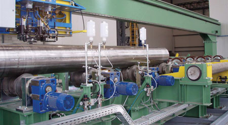
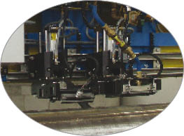
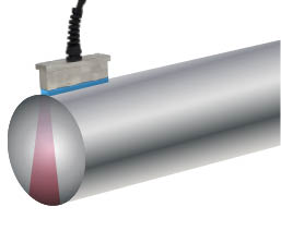
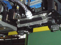
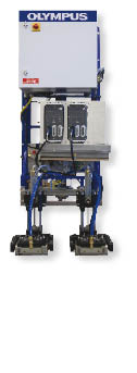
Principle of Inspection Inspection heads are mounted on a carriage, which follows along the length of the billet. Air cylinders are used to move the inspection heads down and up at the beginning/and end of the inspection sequence. The inspection is carried out during the rotation of the billet and the movement of a carriage supporting the inspection heads. Each inspection head is designed with a unique mechanical cluster concept allowing many degrees of freedom to follow billet movement and to maintain an almost perfect coupling, despite significant straightness variations. This specific configuration allows high repeatability of detection, with no need for an inspection tank, resulting in quicker and easier handling of billets.
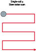
Volume Inspection-Phased Array TechnologyPhased Array vs. Conventional UT With conventional UT, even if a UT paint brush probe can inspect a large area (width) per revolution, there is no physical overlap between the acoustic beam of each probe. This results in a low defect detection rate. Even when 2 rows of conventional UT probes are used to increase the UT beam coverage, a relatively significant inequality of energy density in the billet is still present. This could result in some areas having a lower UT beam energy and lower detection capability for small defects. In addition, using 2 rows of UT probes often results in uncertain mechanical positioning stability.
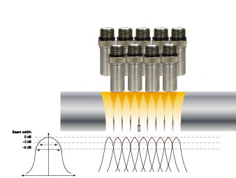
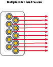
In conventional UT inspections, small defect detection can go as low as -6 dB between two UT beams. In some cases the performance can be worse. Phased array testing is a specialized type of ultrasonic testing that uses sophisticated multielement array transducers and powerful instrumentation/software to steer high-frequency sound beams through the test piece and to map returning echoes. Essentially, a phased array probe is a long conventional UT probe separated into many small elements that are individually excited. A linear electronic scan is performed by moving the acoustic beam along the axis of the array, without any mechanical movement. The beam movement is performed by time multiplexing the active elements.
In phased array inspections, small defect detection is done with no more than a 2 dB variation between two focal laws. When compared to conventional UT solutions for billet inspections, PA can provide:
Internal and Subsurface Defect Inspection
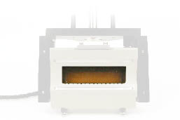
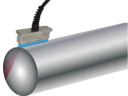
In order to inspect the volume of a large-diameter billet, Olympus has developed a inspection system using phased array technology. This technology detects internal and subsurface defects. Thanks to the unique Olympus water wedge concept and its special elastomer membrane, only a very thin water film is needed between the membrane and the billet surface for ultrasonic coupling. Keeping the water path undisturbed inside the water wedge gives a very high repeatability on a small reference defect. This unique water wedge mechanical concept removes the need for an inspection tank, producing a quicker and an easier handling of billets in the fabrication process and resulting in a higher production capability. Longitudinal Wave INSPECTION Head
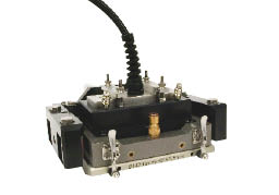
The longitudinal wave (LW) inspection head is dedicated to inspecting internal defects using a phased array probe fixed on a 0° probe holder. SHEAR Wave INSPECTION head
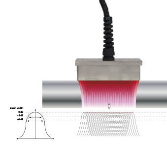
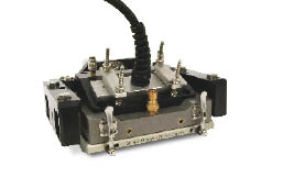
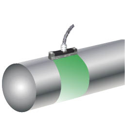
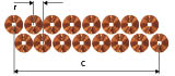
The shear wave (SW) head detects radial cracks close to the surface. The head is similar to the one used for longitudinal inspection but a different probe holders are used to change the mechanical angle of the probes (incident angle) in order to obtain a 45° refraction angle of the UT beam in the billet. Surface Defect InspectionEddy Current Array Principle Eddy current array (ECA) is a nondestructive testing technology used to electronically drive multiple eddy current coils that are placed side by side (with a physical overlap) in the same probe assembly. Each individual eddy current coil in the probe produces a signal relative to the phase and amplitude of the structure beneath it. An EC array probe is made of two rows of coils giving a physical overlap between 2 coils that produce a high resolution of detection. This configuration ensures 100% surface coverage and offers a very high sensitivity due to the small element size. The acquisition unit switches from one coil to the other, firing each of them one by one thus inspecting a large area per revolution. Each individual eddy current coil is connected to the differential mode for an optimized signal-to-noise ratio, even if the inspected surface has been mechanically modified during the fabrication process (for instance, peeling process). The coils are connected in order to have great sensitivity for both longitudinal and transversal direction defects. The major advantage of ECA testing is that a larger area can be scanned in a single-probe pass, while maintaining a high resolution. Surface Defect Inspection
The solution offered by Olympus for detecting surface-breaking defects on large-diameter billets, is based on the eddy current array technology. The ECA inspection is performed by using the same inspection-head mechanical concept as with phased array technology. The only difference is that the water wedge is replaced by a special ECA probe holder allowing in-contact inspection with constant optimized lift-off for any billet diameter. Thanks of the use of carbide strips, the probe is protected against wear or damage making the ECA system well-adapted to the tolerances of semifinished billets as well as finished billets. Each ECA probe can inspect more than 100 mm in area per revolution, and the inspection can be carried out with the same helicoidal sequence as for the PA inspection. The advantages of a solution using a long ECA probe, are similar to those listed when inspecting with multielement PA probes.
Where: n = Number of channels r = Resolution (also depends on the coil configuration) C = Coverage
Inspection-Head Configuration
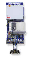
One Inspection Head Basic configuration for one type of technology inspection. Either a 0° water wedge is used for LW UT volume inspection, or eddy current technology is used for surface inspections. Possible configurations:
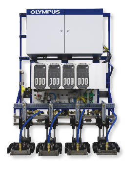
Four Inspection Heads
Full configuration covering 100% volume and surface. One LW inspection head is dedicated to the inspection of internal defects, two SW mode inspection heads (SW+ and SW-) are used to detect radial cracks close to the surface, and one ECA inspection head is used for surface inspection. Furthermore, this carriage configuration can be used to create a mechanical interlacing by using two of the fours available inspection heads with the same technology (ex: 2 LW / 2 ECA or 2LW / SW+ / SW-), which allows to considerably increase inspection productivity. In addition, for some specific requests, more than four inspection heads could be used. Possible configurations:
Two Inspection Heads
Mainly used to combine LW UT and ECA inspection technologies during the same inspection scan sequence. However, this carriage configuration is sometimes used to increase inspection productivity by creating a mechanical interlacing of two inspection heads of the same technology (LW UT or ECA). Possible configurations:
|
- Продукты
- Передовые решения неразрушающего контроля
- Дефектоскопы
- Интегрированные системные решения в области НК
- Толщиномеры
- Компоненты микроскопов
- Оптические измерительные системы
- Видеоскопы, бороскопы
- Высокоскоростные видеокамеры
- Анализаторы XRF и XRD
- Микроскопия
- Semiconductor & Flat Panel Display Inspection
- Инвертированные металлургические микроскопы
- Лазерные конфокальные микроскопы
- Модульные микроскопы
- Объективы
- Опто-цифровые микроскопы
- Поляризационные микроскопы
- Программное обеспечение для анализа изображений
- Прямые металлургические микроскопы
- Стерео микроскопы
- Цифровые камеры
- ПРИМЕНЕНИЕ
- Технологии
- Новости
- события
- Тех.поддержка
- Контакты